Combiloader Toolbox v1.1
Item no.:

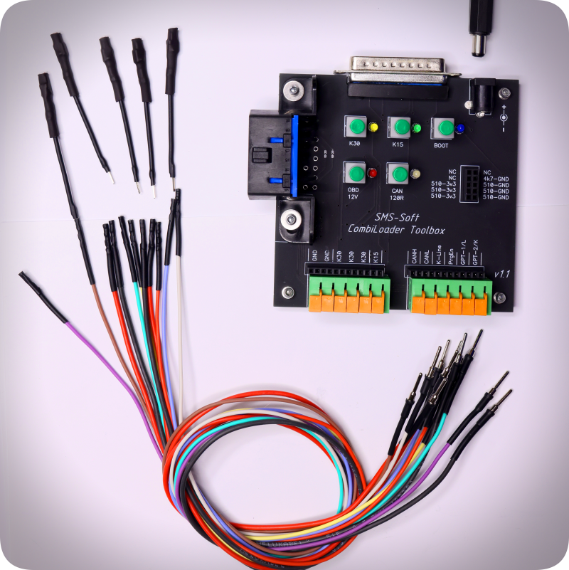
- Combiloader Toolbox
- Wire with connector (colored) – 11 pcs.
- Adapter for connecting large ECU contacts – 5 pcs.
- Power connector, for organizing the connection of an external source.

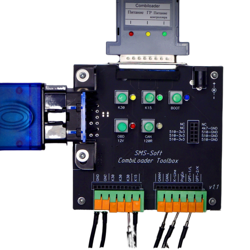
The device is made in the form of an open uncased board, but is fully protected from accidental short circuits, etc. with a plastic screen. All elements are securely fixed.
Connection, switches and contacts.
The upper DB25 connector is designed to connect the V3 bootloader adapter.
Nearby is a 12V power connector (central plus) for connecting a DC power source. It is recommended to use a power source with output voltage regulation within 12 — 15 Volts, with a working load of 3A and control of the consumed current. When using a power supply with overload protection, it is necessary to disable the protection or set the maximum response threshold. The left OBD-II connector for connecting the J2534 adapter. The Toolbox supports correct operation with Dialink and SM2 / SM2Pro adapters.
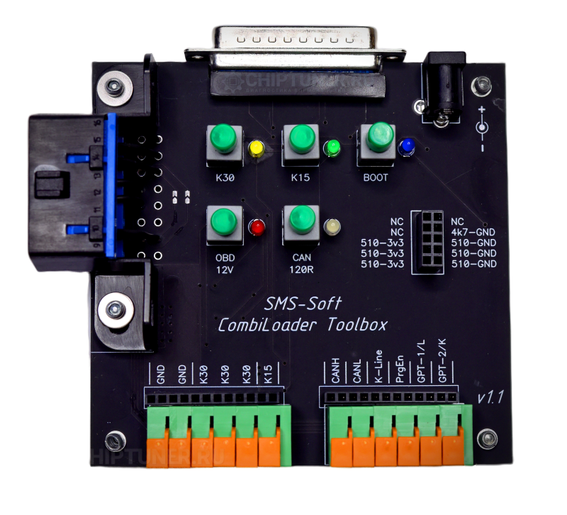
Switches:
K30: supplies constant power to the controller (K30) directly, bypassing the bootloader adapter, and the yellow LED lights up.
K15: supplies switched power to the controller (K15 «Ignition») directly, bypassing the bootloader adapter, and the green LED lights up.
OBD 12V: supplies 12V power to the J2534 adapter, the red LED lights up. Disconnecting the J2534 power supply is only necessary when working with the BSM, if the GPT buses are at 5V. More information on this in the BSM connection tables.
CAN 120R: connects the CAN bus terminator (120 Ohm resistor between CAN-L and CAN-H) to the CAN bus, the connection is indicated by a white LED.
BOOT: manual control of the Boot pins (black connector). The blue LED lights up to indicate that the Toolbox is in manual mode.
The device has a boot connector, which generates seven signals for the boot mode: three — pull-up to 3.3V via a 510 Ohm resistor, three — pull-up to ground (GND) via a 510 Ohm resistor, and one — pull-up to ground (GND) via a 4.7 kOhm resistor. Contacts marked as NC are free, not connected to anything. These boot pins are inactive by default, i.e. not connected to anything, the required signals appear on the connector either automatically, upon command from the bootloader, or forcibly, when the «BOOT» button is pressed.
When turning on the device, all switches except OBD 12V must be turned off to ensure automatic switching of the power lines and bootloader control.
Forced switching on of the power and boot lines is usually not used. In most cases, switching is automatic and is performed by the bootloader. The need to use forced switching on of the power lines is indicated in the programming instructions for some ECUs.
The bottom row of connectors for connecting standard controller buses — GND, K30, K15, CAN, Kline, GPT. The connection is made via special cables and adapters that are included in the kit. When connecting, you just need to insert the wire into the connector — it will be securely fixed. To disconnect the cables, they need to be released by pressing the corresponding lock. The black comb located next to it for a standard pin connector duplicates the main block.
K-Line, brought out to the block — from the bootloader adapter, K-Line from J2534 is marked as GPT-2/K.
For owners of Dialink first releases (up to and including 2019), it is necessary to check the adapter type before starting to use ToolBox, to do this, hold down the Ctrl key while pressing the «ECU Identification» button. If the message «Dialink (Normal)» appears, you do not need to do anything, the device is ready for operation. When receiving the message «Dialink (JmpReq)» you need to solder both jumpers J1 and J2, located next to the OBD-II connector.