

0 items items items
Sum
0
Order details
Total: 0
Shopping cart
3
reasons to choose our shop
Delivery Worldwide delivery
Store warranty for 1 year
11 years and discounts

Motodoc III

Manufacturer
The basic software is free.
TCEPro is an editor for calibration maps of ECUs. To use the software a catalog is required.
Go to module selection
Contents of delivery
  • MotoDocIII electronic unit
  • Secondary voltage cable (DIS-1)
  • DIS-4 cable
  • First-cylinder sensor cable
  • PC communication cable
  • Universal probe cable
  • Pressure sensor cable, 2 pcs.
  • COP sensor power cable
  • Secondary voltage sensor, 4 pcs.
  • Synchronization sensor
  • Pressure sensor (16 atm)
  • 10 kV spark gap
  • Pressure sensor adapter kit, 4 pcs.
  • 'Crocodile' clip (red, black), 2 pcs.
  • Software CD
  • Operating manual
  • DIS-8 cable
  • APPA-32 current clamp
  • Pressure sensor (1 atm)
  • Secondary voltage sensor, 4 pcs.
Basic equipment
Motodoc III — 877 $
+ Add
Status: In stock

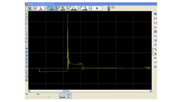
One of the most "advanced" engine analyzers of domestic production — the MotoDoc III universal engine analyzer — is designed for troubleshooting various systems of cars with gasoline engines. The basic kit includes all the sensors required to work with both traditional ignition systems with a high-voltage distributor and electronic energy distribution (DIS and COP).

MotoDoc III can diagnose engines with any fuel system — both injection and carburetor. The device connects to a computer; the device and the diagnostic modes are controlled by the software included in the kit.

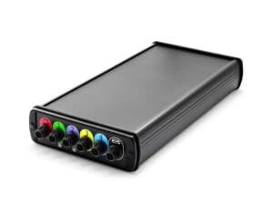
MotoDoc III is very compact, so it can be hung in the engine bay. The sensors connect to the device with short cables, which improves their reliability and noise immunity and makes them much more convenient to use.

The MotoDoc III engine analyzer is designed as a computer add-on. Using a set of connecting wires and sensors, the device connects to the vehicle's electrical circuits. The computer-based approach lets you take advantage of a large monitor screen, the internet and reference materials. The device can be connected to either a desktop computer or a laptop. A sturdy aluminum housing protects the device from temperature and mechanical effects.

Quick-release connectors save the technician's time when connecting cables and sensors. There is no need to look for the key on the connector to insert it. The latch securely holds the cable part and prevents the sensor from coming loose due to vibration. The device is powered from the car battery, and you do not need to think about connection polarity: the device detects the polarity itself and uses the correct terminals. The device can work over a wide range of supply voltages (7-30 V). The device is galvanically isolated from the computer and has a multi-level protection system against high-voltage discharges, short circuits and overvoltage. The device will not fail because of user error.

The high-voltage sensors have a sturdy design and protect the user from breakdowns of the high-voltage wires. With the seven-meter communication cable you can place the measuring unit far from the computer, leaving yourself freedom to move. If desired, the communication cable length can be extended up to 30 meters.

Features

The device effectively identifies faults in the following systems:

Ignition system

  • Checking the condition of spark plugs and spark plug wires (carbon deposits, breaks, breakdowns);
  • Determining operating modes and faults of the ignition coil (inter-turn short circuits, connection correctness check, breakdowns);
  • Diagnostics of ignition system sensors (inductive, Hall);
  • Determining ignition advance angles dynamically (without a stroboscope).


Fuel supply system

  • Electrical testing of fuel injectors (inter-turn short circuits of injector windings, injection phase duration, etc.);
  • Checking sensor operation (temperature, throttle position, O2 sensor, etc.);
  • Checking actuator operation (e.g. the idle speed controller);
  • Joint operation with gas analyzers.

Valve timing system

  • Dynamic compression measurement (on a running engine);
  • Checking the correct installation of the timing belt;
  • Valve operation monitoring.

Other systems

Checking the operation of the alternator and the battery charging system.

Additional features

  • Long data recording time (in oscilloscope mode the recording length is determined by the computer's RAM, and in recorder mode by the free hard disk space);
  • Saving information to a database for the selected customer;
  • Printing reports on the work performed and the faults found.

Hardware specification

  • Device power supply: 9 — 30 V (built-in connection polarity detection);
  • Sampling rate: 10 MHz −1 channel, 5 MHz — 2 channels, 2.5 MHz — 4 channels; Bandwidth per channel: 1.5 MHz ;
  • ADC resolution: 12 bit;
  • Number of channels observed simultaneously: 1,2,3,4;
  • Voltage measurement limits: ±1, ±16, ±160, ±500 V;
  • Input resistance: 500-1000 kOhm;
  • AC-coupled input mode (Channel 1);
  • High-voltage measurement mode ±25 kV;
  • Pressure sensor mode: ±1 atm, ±16 atm, ±100 atm (Channels 1 and 2);
  • Data display rate:
  • 12-18 frames per second without data loss; Connection type to the computer: Ethernet 100 Mbit;
  • Operating system: Windows 2000/XP/VISTA.

System requirements

Minimum:

  • Pentium IV 2 GHz processor
  • 512 MB RAM
  • Ethernet adapter 100 BASE-T
  • Video adapter 1024×600, 256 colors
  • COM port (for connecting a gas analyzer)
  • CD-ROM for installing the software
  • OC Windows 2000/XP

Recommended:

  • Pentium IV 2 GHz processor
  • 1 GB RAM
  • Ethernet adapter 100 BASE-T
  • Video adapter 1024×600, True-Color COM port (for connecting a gas analyzer)
  • CD-ROM for installing the software
  • OC Windows XP

Operating conditions

  • Operating temperature: 0-50°C;
  • Maximum relative humidity: 80% (up to 30°C) and 50% (at 40°C and above).
Registration
×
×
Password recovery
A password reset instruction will be sent to the email you provided during registration.
Recovery
Ready!
An email with a password recovery link has been successfully sent to your email address.
×
Thank you for the subscription!
Your Email has been added to the list. You will be the first to know about all the news!
×
Your message has been sent
Our specialist will contact you as soon as possible.
OK