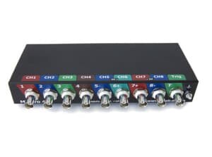
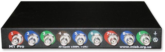
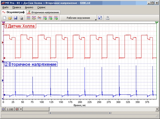
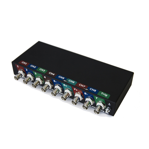
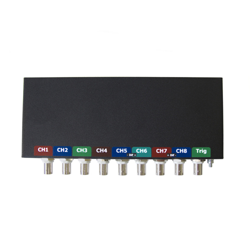
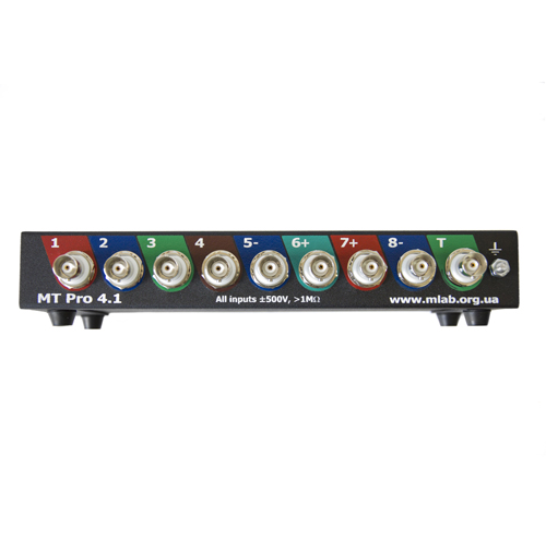
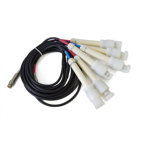
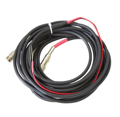
MT Pro is a universal hardware and software package combining the capabilities of an oscilloscope and an engine analyzer.
The MT Pro diagnostic kit effectively detects faults in the following systems:
Ignition system
- Checking the condition of spark plugs and plug wires (carbon deposits, open circuits, breakdowns)
- Determining ignition coil operating modes and faults (inter-turn shorts, connection check, breakdowns)
- Diagnostics of ignition system sensors (inductive, Hall)
- Determining ignition timing angles (without a strobe light)
Fuel supply system
- Electrical testing of fuel injectors (inter-turn shorts in injector windings, injection pulse duration, etc.)
- Checking temperature sensors, throttle position sensor, O2 sensor, mass air flow sensor, etc.
- Checking actuators (idle speed controller, etc.)
Valve timing system
- Estimating relative compression by cylinder in cranking mode
- Measuring compression dynamically (with the engine running) and in cranking mode
- Checking that the timing belt is installed correctly
- Valve operation monitoring
Power supply and charging system
- Checking the alternator and the battery charging system
Starting with version 3.0, the device can:
- Output a set stabilized DC voltage (current up to 100 mA)
- Output various standard signals with adjustable parameters: sine wave, sawtooth, etc.
- Emulate various automotive signals: O2 sensor, crankshaft position sensor, etc.
- Perform linear conversion of the input signal
- PWM generator with adjustable duty cycle and frequency
- PWM generator with voltage-controlled duty cycle and frequency
- PWM generator with smoothly increasing pulse duration
- PWM generator with duty cycle correction of an external PWM
- Measure the active resistance of an injector winding
- Display the waveform of the injector «opening current» and «closing voltage»
Functionality
- Simultaneous on-screen display of data from 1, 2, 3 ... 7, 8 analog channels and 1 logic channel
- Triggering from the signals of virtually any electrical circuit of the vehicle
- Long signal recording time (limited only by available disk space)
- Saving of captured signal data and report support
Specifications
| Analog channels |
| Number of universal analog channels: |
8
1...4 general purpose (250 kHz bandwidth)
5...8 general purpose (1 MHz bandwidth) |
| Number of channels enabled simultaneously: |
1, 2, 3, 4, 5, 6, 7, 8 |
| Number of hardware sub-ranges per channel: |
12 |
| Hardware sub-ranges per channel: |
±0.1, ±0.2, ±0.5, ±1, ±2, ±5, ±15, ±30, ±50, ±100, ±200 and ±500 V |
| Additional amplifiers x1, x2, x5, x10: |
in channels 6 and 8 |
| Channel input resistance: |
not less than 1 MOhm |
| Optional pseudo-differential input: |
channel 6 — channel 5, channel 8 — channel 7 |
| |
|
| Sync channel |
| Number of universal sync channels: |
1 |
| Number of hardware sub-ranges per channel: |
12 |
| Hardware sub-ranges per channel: |
±0.1, ±0.2, ±0.5, ±1, ±2, ±5, ±15, ±30, ±50, ±100, ±200 and ±500 V |
| Channel input resistance: |
not less than 1 MOhm |
| Operating modes: |
low-frequency analog channel
negative pulse detector
positive pulse detector |
| |
|
| Maximum sampling rate1) |
| In oscilloscope and recorder mode: |
6 MHz (in 1-channel mode)
3 MHz (in 2-channel mode)
2 MHz (in 3-channel mode)
1 MHz (in 4...6-channel mode)
500 kHz (in 7...8-channel mode) |
| |
|
| ADC resolution2) |
| In oscilloscope and recorder mode: |
12 bit |
| |
|
| Galvanic isolation |
| Isolation test voltage: |
1KV for 60 seconds |
| Insulation resistance: |
not lower than 1000 MOhm |
| Isolation capacitance: |
not higher than 60 pF |
| |
|
| Operating modes |
| Oscilloscope (functionally similar to a conventional analog oscilloscope) |
| Frame-by-frame (the data of each measurement (frame) is displayed on the PC screen in real time and automatically saved to the hard drive for later viewing / analysis) |
| Recorder (measurement data is displayed on the PC screen in real time and written to the hard drive as a continuous stream for later viewing / analysis) |
| |
|
| Other specifications |
| Supply voltage3): |
5-25 volts (more about the external power supply...) |
| Power consumption: |
not more than 1.2 W |
| PC interface: |
Ethernet 100M (cable length 10-20 m) |
| Dimensions of the measuring unit: |
204×83×33 mm |
| Weight of the measuring unit: |
not more than 0.6 kg |
Notes:
- The logic channel is functionally similar to an analog channel, except that the input signal goes not to the ADC but to a comparator with a threshold that can be set from the shell. The logic channel output equals «1» if the input voltage exceeds the set comparison threshold, and «0» if it does not. This allows the logic channel to be used (without reducing the sampling rate) for synchronization and marking, thereby «saving» an analog channel that would otherwise be used for such purposes.
- The maximum sampling rate depends only on the number of enabled analog channels; the number of enabled logic channels does not affect the maximum sampling rate
- Thanks to the use of 8 sub-ranges, the overall measurement accuracy increases 8-fold.
- Memory depth decreases in proportion to the number of enabled analog channels.
- Memory depth in recorder mode is limited by available disk space and a maximum file size of 4 GB
- Provided that disk space is available.
Main differences between MT Pro 4.1 and MT Pro 4 1
The power supply unit has been completely redesigned.
- Supply voltage: +5±0.5 volts / 350 mA.
- Added protection against: reverse polarity, overvoltage and supply voltage ripple; if the permissible supply voltage is exceeded for a long time, the protective fuse resistor will burn out; a short-term voltage spike will cause no harm.
- Galvanic isolation of the power supply has been implemented, i.e. the power source, for example a PC USB port, is galvanically isolated from the device's measuring circuits.
- The supplied patch cord has the device's power line from the PC USB port built in, i.e. data exchange (high noise immunity of Ethernet) and power (galvanic isolation) run over a single cable.
The device's LAN port has been reworked to work properly with older PCs over a Straight-through patch cord. Network cards, for example those based on the Realtek RTL8139 chipset, do not support Auto-MDI/MDI-X (automatic selection of straight or crossover twisted-pair wiring), which meant having to look for a Cross-over patch cord, which is not often found on sale.
The MT Pro diagnostic kit effectively detects faults in the following systems:
Ignition system
- Checking the condition of spark plugs and plug wires (carbon deposits, open circuits, breakdowns)
- Determining ignition coil operating modes and faults (inter-turn shorts, connection check, breakdowns)
- Diagnostics of ignition system sensors (inductive, Hall)
- Determining ignition timing angles (without a strobe light)
Fuel supply system
- Electrical testing of fuel injectors (inter-turn shorts in injector windings, injection pulse duration, etc.)
- Checking temperature sensors, throttle position sensor, O2 sensor, mass air flow sensor, etc.
- Checking actuators (idle speed controller, etc.)
Valve timing system
- Estimating relative compression by cylinder in cranking mode
- Measuring compression dynamically (with the engine running) and in cranking mode
- Checking that the timing belt is installed correctly
- Valve operation monitoring
Power supply and charging system
- Checking the alternator and the battery charging system
Starting with version 3.0, the device can:
- Output a set stabilized DC voltage (current up to 100 mA)
- Output various standard signals with adjustable parameters: sine wave, sawtooth, etc.
- Emulate various automotive signals: O2 sensor, crankshaft position sensor, etc.
- Perform linear conversion of the input signal
- PWM generator with adjustable duty cycle and frequency
- PWM generator with voltage-controlled duty cycle and frequency
- PWM generator with smoothly increasing pulse duration
- PWM generator with duty cycle correction of an external PWM
- Measure the active resistance of an injector winding
- Display the waveform of the injector “opening current” and “closing voltage”
Functionality
- Simultaneous on-screen display of data from 1, 2, 3 …7, 8 analog channels and 1 logic channel
- Triggering from the signals of virtually any electrical circuit of the vehicle
- Long signal recording time (limited only by available disk space)
- Saving of captured signal data and report support
Specifications
| Analog channels |
| Number of universal analog channels: |
8
1…4 general purpose (250 kHz bandwidth)
5…8 general purpose (1 MHz bandwidth) |
| Number of channels enabled simultaneously: |
1, 2, 3, 4, 5, 6, 7, 8 |
| Number of hardware sub-ranges per channel: |
12 |
| Hardware sub-ranges per channel: |
±0.1, ±0.2, ±0.5, ±1, ±2, ±5, ±15, ±30, ±50, ±100, ±200 and ±500 V |
| Additional amplifiers x1, x2, x5, x10: |
in channels 6 and 8 |
| Channel input resistance: |
not less than 1 MOhm |
| Optional pseudo-differential input: |
channel 6 - channel 5, channel 8 - channel 7 |
| |
|
| Sync channel |
| Number of universal sync channels: |
1 |
| Number of hardware sub-ranges per channel: |
12 |
| Hardware sub-ranges per channel: |
±0.1, ±0.2, ±0.5, ±1, ±2, ±5, ±15, ±30, ±50, ±100, ±200 and ±500 V |
| Channel input resistance: |
not less than 1 MOhm |
| Operating modes: |
low-frequency analog channel
negative pulse detector
positive pulse detector |
| |
|
| Maximum sampling rate1) |
| In oscilloscope and recorder mode: |
6 MHz (in 1-channel mode)
3 MHz (in 2-channel mode)
2 MHz (in 3-channel mode)
1 MHz (in 4…6-channel mode)
500 kHz (in 7…8-channel mode) |
| |
|
| ADC resolution2) |
| In oscilloscope and recorder mode: |
12 bit |
| |
|
| Galvanic isolation |
| Isolation test voltage: |
1KV for 60 seconds |
| Insulation resistance: |
not lower than 1000 MOhm |
| Isolation capacitance: |
not higher than 60 pF |
| |
|
| Operating modes |
| Oscilloscope (functionally similar to a conventional analog oscilloscope) |
| Frame-by-frame (the data of each measurement (frame) is displayed on the PC screen in real time and automatically saved to the hard drive for later viewing / analysis) |
| Recorder (measurement data is displayed on the PC screen in real time and written to the hard drive as a continuous stream for later viewing / analysis) |
| |
|
| Other specifications |
| Supply voltage3): |
5-25 volts (more about the external power supply...) |
| Power consumption: |
not more than 1.2 W |
| PC interface: |
Ethernet 100M (cable length 10-20 m) |
| Dimensions of the measuring unit: |
204 x 83 x 33 mm |
| Weight of the measuring unit: |
not more than 0.6 kg |
Notes:
- The logic channel is functionally similar to an analog channel, except that the input signal goes not to the ADC but to a comparator with a threshold that can be set from the shell. The logic channel output equals “1” if the input voltage exceeds the set comparison threshold, and “0” if it does not. This allows the logic channel to be used (without reducing the sampling rate) for synchronization and marking, thereby “saving” an analog channel that would otherwise be used for such purposes.
- The maximum sampling rate depends only on the number of enabled analog channels; the number of enabled logic channels does not affect the maximum sampling rate
- Thanks to the use of 8 sub-ranges, the overall measurement accuracy increases 8-fold.
- Memory depth decreases in proportion to the number of enabled analog channels.
- Memory depth in recorder mode is limited by available disk space and a maximum file size of 4 GB
- Provided that disk space is available.
Main differences between MT Pro 4.1 and MT Pro 4 1
The power supply unit has been completely redesigned.
- Supply voltage: +5±0.5 volts / 350 mA.
- Added protection against: reverse polarity, overvoltage and supply voltage ripple; if the permissible supply voltage is exceeded for a long time, the protective fuse resistor will burn out; a short-term voltage spike will cause no harm.
- Galvanic isolation of the power supply has been implemented, i.e. the power source, for example a PC USB port, is galvanically isolated from the device's measuring circuits.
- The supplied patch cord has the device's power line from the PC USB port built in, i.e. data exchange (high noise immunity of Ethernet) and power (galvanic isolation) run over a single cable.
The device's LAN port has been reworked to work properly with older PCs over a Straight-through patch cord. Network cards, for example those based on the Realtek RTL8139 chipset, do not support Auto-MDI/MDI-X (automatic selection of straight or crossover twisted-pair wiring), which meant having to look for a Cross-over patch cord, which is not often found on sale.