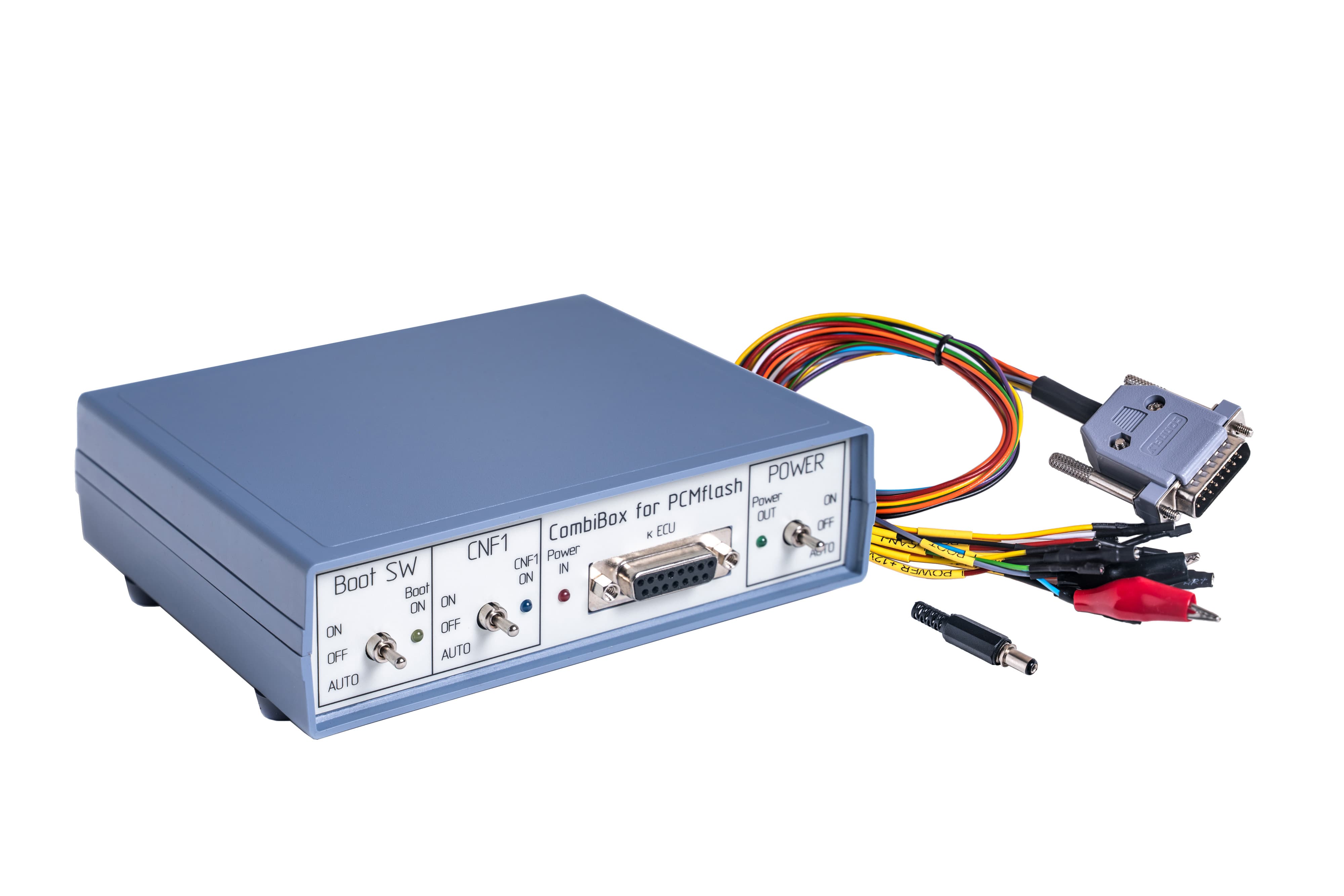


CombiBox is designed to connect an ECU to PCMflash and a J2534 device on the bench and to switch power and GPT1, GPT2 signals, and to form BOOT, CNF1 signals. When used with Scanmatik 2 PRO CombiBox for PCMflash allows to form GPT1, GPT2 signals necessary to work with Module 53 and Module 71, and future modules.
Power
CombiBox requires constant 12V supply voltage. The mating part of the connector is included in the delivery package. It is utterly important to respect polarities when arranging soldered connections of the power cable. Incorrect power supply is EXTREMELY DANGEROUS and may cause the CombiBox or the control unit connected to it to fail. It is recommended to use regulated laboratory power supplies with voltage adjustment range up to 30V and with a maximum current of not less than 3A to safely operate CombiBox and program ECUs.
Connection
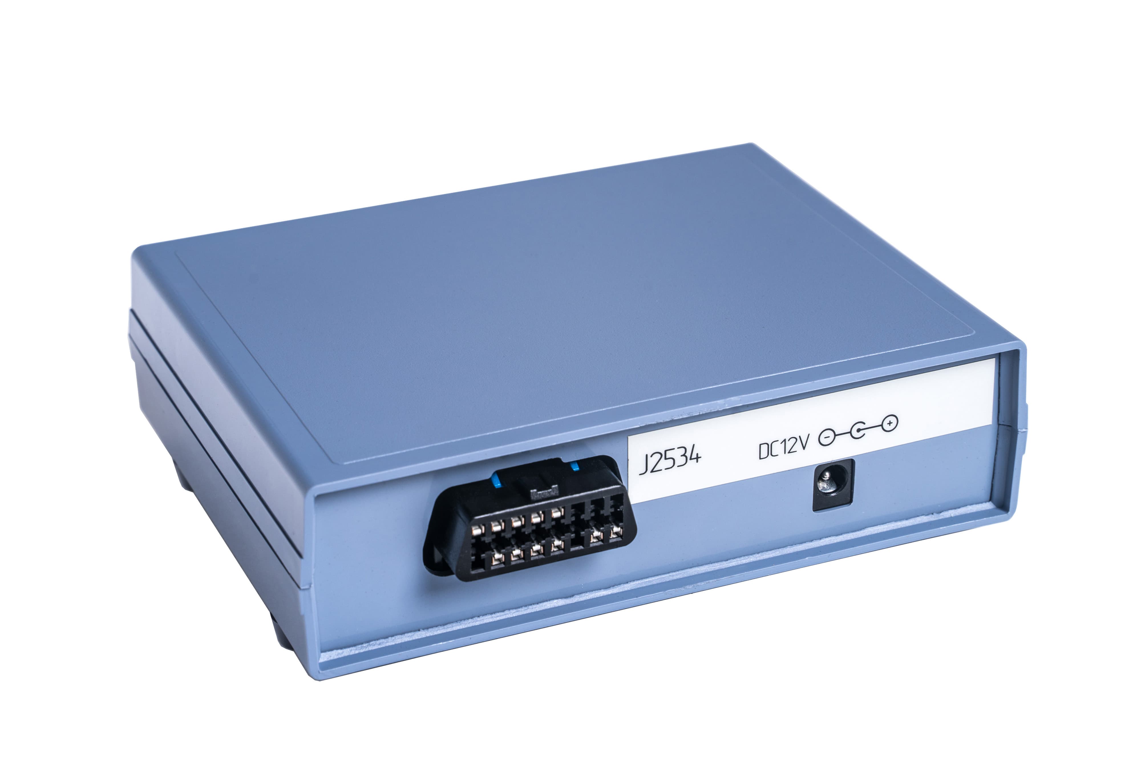
On the back of the CombiBox there are 2 plugs:
1. J2534 is a plug for connecting a J2534 device (Scanmatik 2 PRO).
The plug has the following connection diagram:
- 1 — GPT1
- 2 — GPT2
- 4 — GND
- 5 — GND
- 6 — CAN-H
- 7 — K-LINE
- 14 — CAN-L
- 15 — L–LINE
- 16 — +12V
2. DC IN 5A Max Jack is a plug for connecting power supply.
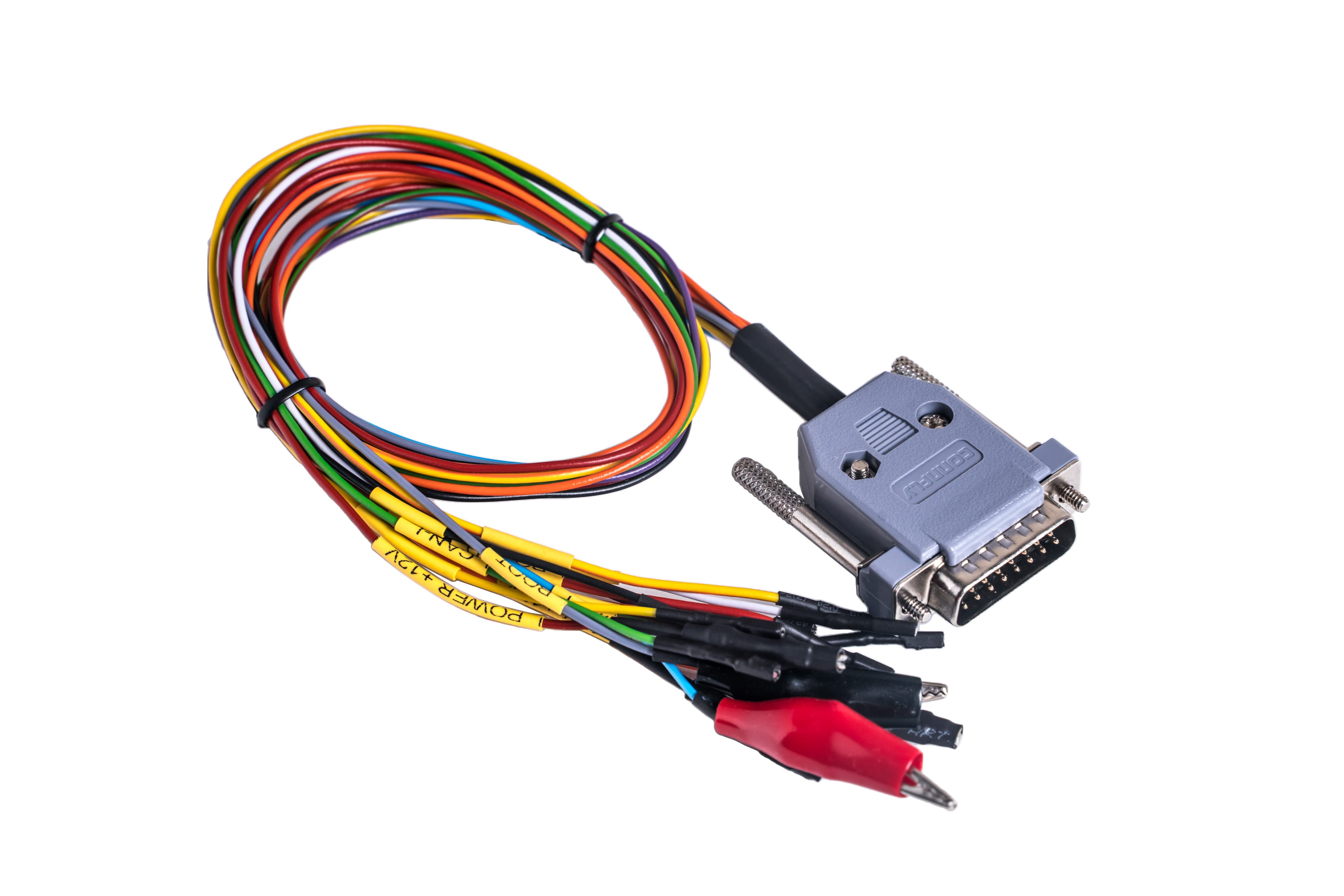
On the front panel of the device there is a DB-15 plug designed to connect to the ECU using a universal cable. All cable wires have appropriate markings to connect them correctly.
The plug has the following connection diagram:
- 2 — Purple, VPP;
- 3 — Green brown, GPT2;
- 4 — Blue, CNF1;
- 5 — Red, VECU +12V;
- 7 — White, CAN-H;
- 9 — Orange, VKEY +12V;
- 10 — Grey, BOOT;
- 11 — Black, GND;
- 12 — Yellow Orange, GPT1;
- 14 — Yellow, K-Line;
- 15 — Green, CAN-L.
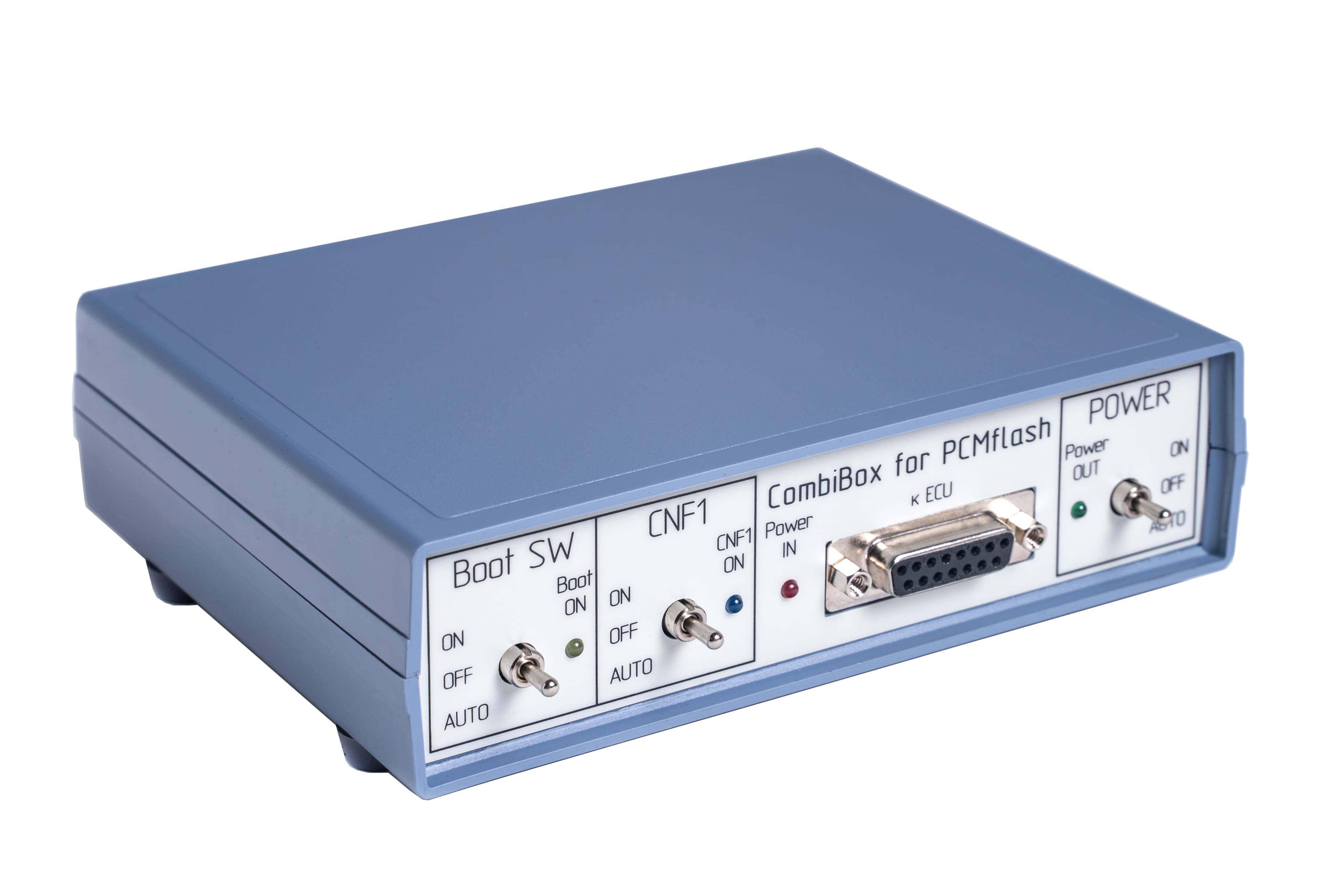
Controls elements
«POWER» switch, power control. The device has three modes of power supply to the ECU:
- «OFF», allows to remove all power and control signals from the DB-15 connector.
- «ON», power is supplied to VECU and VKEY terminals, as well as control outputs depending on the chosen operation mode of the BOOT switch.
- «AUTO», in this mode, power management is performed by the PCMflash.
Boot SW switch, BOOT signal control:
- «OFF», allows to remove all control signals from the DB-15 connector;
- «ON», pulls BOOT up to the signal minus;
- «AUTO», in this mode, simultaneous control of signals is performed by the PCMflash.
«CNF1» switch, CNF1 signal control (3.3V):
- «OFF», allows to remove all control signals from the DB-15 connector;
- «ON», pulls CNF1 up to +3.3 V;
- «AUTO», in this mode, simultaneous control of signals is performed by the PCMflash.
The device has built-in current-limiting resistors on signal lines:
- «BOOT» — 1000 Ohm;
- «CNF1» — 510 Ohm;
- «CAN» — 120 Ohm.
Indicators:
- The «Power IN» LED indicates the presence of the supply voltage;
- The «Power OUT» LED indicates the presence of the voltage on the ECU;
- The «Boot ON» LED indicates pull-ups on BOOT;
- The «CNF1 ON» LED indicates pull-ups on CNF1.