PowerBox for Combiloader Tricore
Item no.:

- Adapter

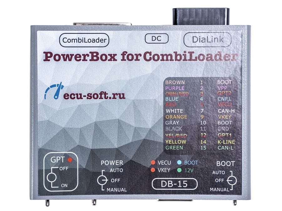
This device is designed to connect an ECU to a flashing tool on the bench and to switch the supply voltage and GPT1, GPT2, as well as to generate of BOOT, CNF1 signals. It is compatible with CombiLoader in the automatic mode.
Controls:
The device is equipped with three switches to provide operation in different modes.
- GPT When this mode is activated, the signal lines 7 and 15 of the DiaLink connector are switched to the DB-15 connector (GPT1 and GPT2), and the power is simultaneously removed from the DiaLink connector. Used when reading a password in GPT mode. In the off state, the signal lines 7 and 15 are output to the DB-15 connector (K-line and L-line), and the GPT1 and GPT2 lines are made dead.
- POWER, power control. The device has three modes of power supply to the ECU:
- OFF, allows you to remove all power and control signals from the DB-15 connector;
- MANUAL, supplies power to the VECU and VKEY terminals, as well as to the control outputs, depending on the selected tactics of the BOOT switch;
- AUTO, automatic control, in this mode, the power is controlled by the CombiLoader.
- BOOT , simultaneous control of BOOT and CNF1 signals (3.3V):
- OFF, allows you to remove all power and control signals from the DB-15 connector;
- MANUAL, on, pulls up the BOOT to the signal minus, and CNF1 to 3.3V;
- AUTO, automatic control, in this mode, the power is controlled by the CombiLoader.
The device has built-in current-limiting resistors on the signal lines:
- RESET— 510Ω
- BOOT — 510Ω
- CNF1 — 510Ω
- CAN — 120Ω
Connectors
The device is equipped with connectors for hardware peripherals. DC connector is designed to power the embedded circuitry of the device, as well as the connected ECU. Only quality power supplies with an output voltage of 12V are recommended. When reading the password when it is impossible on the car, you need to take into account that high-voltage converters in the ECU at the start consume a sufficiently large current, which can trigger a protection operation or even cause damage to the power supply.
J2534 connector is designed to connect a J2534interface with the OBD-II connector. The connector has the following wiring diagram:
- 4 GND
- 5 GND
- 6 CAN-H
- 7 K-LINE
- 13 VPP
- 14 CAN-L
- 15 L-LINE
- 16 POWER
DB-15 connector is designed for connecting the ECU.
14P600KT02, 14P600KT03 or equivalent cables are recommended. The connector has the following wiring diagram:
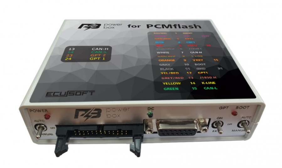
- 1 RESET BROWN
- 2 VPP PURPLE
- 3 GPT2 ORANGE
- 4 CNF1 BLUE
- 5 VECU RED
- 7 CAN-H WHITE
- 9 VKEY ORANGE
- 10 BOOT GRAY
- 11 GND BLACK
- 12 GPT1 YELLOW / RED
- 14 K-LINE YELLOW
- 15 CAN-L GREEN Indicators.
The GPT LED indicates activation of the mode of the same name.
The VECU, VKEY LED indicators indicate the presence of voltage VECU and VKEY.
The 12V LED indicator indicates the presence of supply voltage. The BOOT LED indicates pull-ups on CNF1 and BOOT.

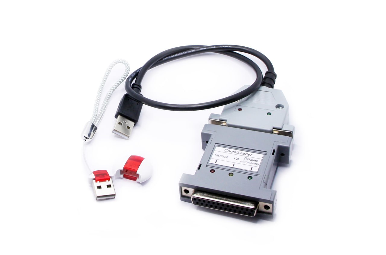
The universal cable DB15-PIN allows to connect to various ECU connectors, it is a better equivalent of 14P600KT02. GPT1 and GPT2 of the same colour are labelled and brought out together with additional CAN-H CAN-L. The cable has an extra pair of pins on the VECU chain and an extra pair of pins on the VKEY chain which allows to apply up to 8 supply voltages (four small pins and 4 big ones).