PowerBox for PCMflash
Item no.: 13P3000

- Tool (without the cables)

PowerBox for PCMflash is designed to connect the control unit to the software bootloader "on the bench" and automatic (if supported by the flasher and the J2534 adapter) or manual switching of supply voltages and generation of RESET, BOOT, CNF1, GPT1, GPT2, WATCHDOG signals.
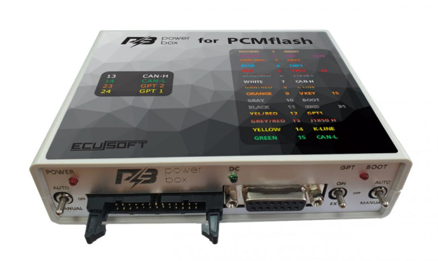
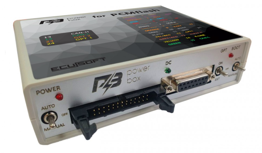
Model 2022 (has a new switch arrangement, see photo in the description) of the year of release has an improved GPT signal generator. For devices of previous generations, we recommend using GPT BOOSTER.
Compatible in automatic mode with bootloaders that use for control:
BOOT - OEM12, 12 contact OBD-II.
Power supply control - L-LINE, 15 contact OBD-II.
Important:
To work with 71 and 77 PCMflash modules, the BOOT switch must be in the AUTO or MANUAL position. (The BOOT indicator should light when power is supplied to the ECU).
In MANUAL mode - power must be supplied by the switch on the PowerBox, and not from an external source.
In GPT mode, it allows you to work with 5V and 12v signals, as well as with differential inputs without using capacitors.
Controls:
The device is equipped with three switches to ensure operation in different modes.
- Switch - POWER, power management.
- The device has three modes of power supply to the ECU:
- OFF, off, allows you to remove all power signals from the IDC-26 and DB-15 connectors.
- MANUAL, on, supplies power to the VECU and VKEY terminals, as well as to the control outputs depending on the selected operating tactics.
- AUTO, automatic control, in this mode, power control is performed by the bootloader with the L-Line signal (15 OBD-II contact).
- BOOT switch, simultaneous control of BOOT, RESET and CNF1 signals (3.3 volts):
- OFF, disabled, allows you to remove all control signals from the DB-15 connector.
- MANUAL, enabled, pulls RESET and BOOT to the signal minus, and CNF1 to +3.3 volts.
- AUTO, automatic control, in this mode, the bootloader (OBD-II contact 12, OEM12) simultaneously controls the BOOT, RESET and CNF1 signals.
- For the built-in generator to work with the 71 and 77 PCMflash modules, the BOOT switch must be in the MANUAL or AUTO position (the BOOT LED must be lit).
- GPT switch:
- OFF, disabled, allows you to remove all control signals on the GPT signal lines. Can be used for diagnostics and "OBD programming".
- ON, the built-in GPT generator is used.
- EXT, the GPT signal is used directly from the OBD-II connector (the signal is generated by scanmatik).
- You cannot use the GPT signal from the device to connect directly to the processor signal circuits on the ECU board.
The device has built-in current-limiting resistors on the signal lines:
- BOOT BROWN - 5.1 KOhm (Recommended for Infineon C16X and ST10 family)
- BOOT GRAY - 510 Ohm (Recommended for TriCore)
- CNF1 - 220 Ohm
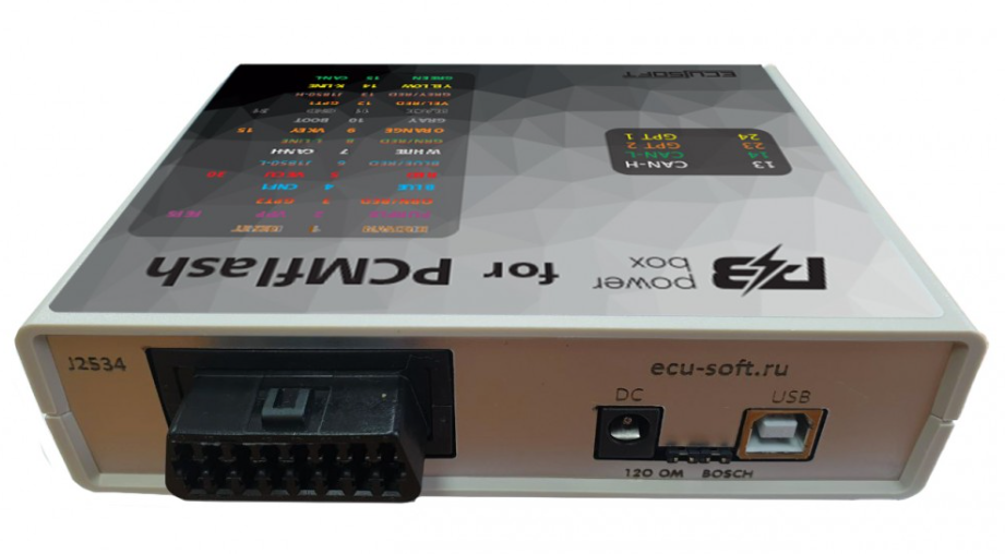
The CAN bus has a 120 Ohm terminal resistor, which can be disconnected if necessary - remove the jumper of the same name (located closer to the DC connector).
BOSCH jumper (located closer to the USB connector) - to work with the BOSCH unit in GPT mode, to work with SIMOS12 / SIMOS18 units in GPT mode, you need to remove this jumper.
Connectors:
The device is equipped with multi-purpose connectors, which allows flexible connections.
The USB connector is designed for connecting to a computer. The connector requires connection when using the built-in USB-UART converter, for updating the PowerBox device software, and when programming Renesas processors.
The DC connector is designed to power the built-in circuit of the device, as well as the connected ECU. Only high-quality power supplies are recommended for use. The central pin is for +, the side pin for -. There is input protection against incorrect polarity. When reading the password, when this is not possible on a car, it must be taken into account that high-voltage converters in the ECU consume quite a large current at startup, which can lead to the protection being triggered or even cause the power supply to break down.
The J2534 connector
The connector has the following connection diagram:
1 GPT1 EXT
2 GPT2 EXT / J1850
4 GND
5 GND
6 CAN-H
7 K-LINE
10 J1850
12 SELECT BOOT
13 VPP
14 CAN-L
15 L-LINE
16 POWER
DB-15 connector
It is recommended to use the DB15 - PIN cable.
The connector has the following connection diagram:
1 BOOT BROWN
2 VPP PURPLE
3 GPT2
4 CNF1 BLUE
5 VECU RED
6 J1850 L
7 CAN-H WHITE
9 VKEY ORANGE
10 BOOT GRAY
11 GND BLACK
12 GPT1
13 J1850 H
14 K-LINE YELLOW
15 CAN-L GREEN
IDC-26 connector
The connector has the following connection diagram:
1 GND SIGNAL
2 VECU
3 VPP (Pin 13 OBD-II, OEM13)
5 5V
6 GND
7 RXD
8 TXD
10 WATCHDOG
11 5V
12 K-LINE
13 CAN-H
14 CAN-L
15 GND
21 GND
23 GPT2
24 GPT1
Indicators:
The POWER LED indicates that power is supplied to the ECU. Flashing of the indicator indicates unstable power supply of the device, it is recommended to de-energize the device for at least 1 minute.
The DC LED indicates the presence of supply voltage.
The BOOT LED indicates the presence of 3.3 volts at the CNF1 output, pull-ups to minus on BOOT and RESET, and also indicates the GPT mode (lit - 71 or 77 module \ off - 53 module).


The universal cable DB15-PIN allows to connect to various ECU connectors, it is a better equivalent of 14P600KT02. GPT1 and GPT2 of the same colour are labelled and brought out together with additional CAN-H CAN-L. The cable has an extra pair of pins on the VECU chain and an extra pair of pins on the VKEY chain which allows to apply up to 8 supply voltages (four small pins and 4 big ones).